
Grounding Braid Selection for Wind Turbine Lightning Protection
Wind turbines are 'natural lightning rods' – an 80-160m tower standing isolated in the open has a lightning strike probability 5-10 times that of ground buildings. IEC 61400-24 requires wind turbines to ensure safety under a 200kA lightning current – and the grounding braid, as the 'last meter channel' for lightning to enter the ground, if the cross-section is insufficient or the connection is loose, the lightning current instantly vaporizes the braid → the grounding system disconnects → the lightning current enters the nacelle along cables and control lines → damages the generator and converter, causing losses of hundreds of thousands per incident.
RISK AUDIT // ENGINEERING DIAGNOSIS
Procurement Pitfall Guide
"Flange bridging failures that ground your turbine—and your revenue."
QC-AUDIT // REV.5
SCALE 1:1 · 03 ITEMS
RISK-01
Insufficient Cross-Section of Tower Flange Bridging Braid Leads to Lightning Burnout
Corrective Measures
RISK-02
Improper Braid Coating Selection Leads to Connector Oxidation
Corrective Measures
RISK-03
The 'Rotating Grounding' from Blade to Hub is a Unique Challenge for Wind Power
Corrective Measures
FIELD-SPECIFIC INSIGHT
Critical Checkpoints for Grounding Braid Procurement
The most overlooked engineering difference in wind turbine grounding braid selection is the coating's impact on long-term contact resistance in corrosive environments. While cross-section is often specified per lightning class, the coating (tinned vs silver-plated) and the use of conductive grease determine whether the connection remains reliable over the turbine's 20+ year life.
WHAT TO CHECK
- 1Tinned copper braid (≥8μm tin) is adequate for C3 inland environments but in C4 coastal or C5-M offshore, tin can oxidize to increase contact resistance; silver-plated braid maintains <1μΩ·cm² contact resistance even in salt spray.
- 2Flange bridging braid cross-section must be at least 35mm² for 150kA (Class II) and 50mm² for 200kA (Class I); using 16mm² can cause instant vaporization under lightning current.
- 3Dissimilar metal contact (copper braid to steel flange) requires conductive grease to prevent galvanic corrosion; copper-based grease for inland, silver-based for offshore to keep contact resistance below 5μΩ·cm².
- 4Rotating grounding from blade to hub is a unique wind power challenge – the pitch bearing oil film is non-conductive; a dedicated rotating grounding device must be specified, not just a static braid.
| Check | Why it matters | What to specify |
|---|---|---|
| Cross-section vs lightning class | Insufficient cross-section causes braid vaporization under lightning current, disconnecting the grounding path and leading to equipment damage. | Specify 35mm² for Class II (150kA) and 50mm² for Class I (200kA) per IEC 62305; for offshore, use 70mm² or double 50mm² for redundancy. |
| Coating material and thickness | Tin coating ≥8μm prevents copper oxidation in C3 environments; silver plating provides lower and more stable contact resistance in C4/C5-M environments. | For inland: T2 tinned copper ≥8μm. For coastal/offshore: silver-plated copper or tinned copper with silver-based conductive grease. |
| Conductive grease application | Without grease, copper-steel contact oxidizes, increasing resistance from <0.1mΩ to >10mΩ, exceeding IEC 62305-3's ≤0.2Ω requirement. | Apply copper-based grease (contact resistance <5μΩ·cm²) for inland; silver-based grease (<1μΩ·cm²) for offshore at all connection surfaces. |
| Rotating grounding device | Blade lightning strikes (80%+ of strikes) must pass through pitch bearing; oil film is non-conductive, so without rotating grounding, lightning destroys pitch control electronics. | Include a dedicated rotating grounding device rated for 200kA, with redundant brush contacts and continuous monitoring of resistance. |
All cross-section and coating recommendations are based on IEC 61400-24 and IEC 62305 series. Actual lightning current parameters may vary by site; verify with project-specific lightning risk assessment.
Evidence level: standard-backed
INDUSTRY TECH REFERENCE
From Corrosion to Out-of-Spec Grounding: The Escalation
Take crimped terminals and flange-bridging joints as examples. In salt-spray environments failure is not sudden — it escalates along this chain:
- 1Salt settles: airborne chloride deposition starts at ISO 9223 class S2 (60–300 mg/m²·day), packing into terminal and lap micro-gaps
- 2Crevice corrosion starts: micro-gaps plus seawater → deoxygenated, acidified — even 316L pits; the same joint corrodes about 5–10× faster offshore than onshore (magnitude estimate)
- 3Section shrinks: corrosion eats the effective conductive area, ground resistance climbs and breaks the ≤4Ω acceptance line (grounding flat steel and bolts basis)
- 4Strand breakage adds on: fatigue cracks at repeated-bend points start from surface defects, invisible and warning-free — resistance is usually already over limits when found
- 5Countermeasures: re-measure against ≤4Ω and strip-check terminals on schedule; offshore, move straight to the 316L/2205 material tier
The S2-class chloride deposition of 60–300 mg/m²·day follows ISO 9223 (KB-sourced); the 5–10× offshore corrosion ratio is a magnitude estimate.
INDUSTRY TECH REFERENCE
Grounding Parts Ordering: Spec, Material, Acceptance
Before ordering grounding parts, pin down these three numbers first — then talk plans and pricing.
M10–M16 follows the industry scene-spec table (KB §7); verify against project design.
INDUSTRY TECH REFERENCE
Three Signs of a Failing Ground Connection
Strand breakage and corrosion do not show on the surface — catch grounding failure by signals, not by eye.
- Resistance signal: re-measure ground resistance against ≤4Ω; when it drifts over, strip-check the terminals — suspect corrosion and strand breakage first
- Time signal: crevice corrosion and fatigue strand breakage are slow variables — do not skip the annual inspection; offshore units move to the 316L/2205 material tier
- Location signal: joints spread across every flange of the 4–6 tower sections and the nacelle — the highest sit near 80–100 m, and offshore work also waits on a wave-height window below 1.5 m (magnitude estimate)
The 1.5 m wave-height window is a magnitude estimate; 80–100 m follows the KB service-height basis; the 4–6 tower sections are the KB structural description.
INDUSTRY TECH REFERENCE
Match the Material to the Life Window
Grounding hardware material is not about spending more — match it to the turbine life window first, then pick the tier.
Turbine design life runs 20–25 years onshore and 25–30 years offshore (industry magnitude) — match grounding hardware material and terminals to this window: 316L/2205 offshore in C5-M, 304 or hot-dip zinc inland; keep acceptance and inspection aligned to the ≤4Ω criterion. Budgeting replacement cost across the 20–30-year window beats optimizing the unit price.
The 20–25/25–30-year design life is an industry magnitude estimate.
PLAN COMPARISON
Three-Plan Core Parameter Comparison
Compare row by row. Click column headers to jump to plan details.
| A · Plan A · Inland Wind Farm Standard Grounding | B · Plan B · Coastal/High Lightning Area Enhanced Grounding | C · Plan C · Offshore Wind Farm / Highest Grade | |
|---|---|---|---|
| 1. COPPER BRAID GROUNDING STRAP | |||
| SPEC | 35mm² Tinned | 50mm² Tinned Double | 50mm² Silver-Plated |
| MATERIAL | T2 Tinned Copper ≥8μm | T2 Tinned Copper | T2 Silver-Plated Copper |
| GRADE | IEC 62305 Class II | IEC 62305 Class I | IEC 62305 Class I+ |
| FINISH | HDG >=55um per ISO 1461 | HDG >=55um per ISO 1461 | HDG >=55um per ISO 1461 |
| 2. COPPER BRAID GROUNDING STRAP (TOWER BASE) | |||
| SPEC | 50mm² Tinned | 70mm² Tinned | 50-70mm² |
| MATERIAL | T2 Tinned Copper | T2 Tinned Copper | 316L Stainless Steel |
| GRADE | IEC 62305 | IEC 62305 Class I | A4-80 |
| FINISH | HDG >=55um per ISO 1461 | HDG >=55um per ISO 1461 | HDG >=55um per ISO 1461 |
| 3. COPPER TERMINAL | |||
| SPEC | 35/50mm² Hydraulic Crimp | 100g/tube | 50g/tube |
| MATERIAL | T2 Tinned Copper | Copper-Based | Silver-Based |
| GRADE | / | Contact Resistance <5μΩ·cm² | Contact Resistance <1μΩ·cm² |
| FINISH | HDG >=55um per ISO 1461 | HDG >=55um per ISO 1461 | HDG >=55um per ISO 1461 |
SELECTION GUIDE
Still deciding which grounding plan fits your site?
| Operating condition | Recommended option | Key basis |
|---|---|---|
| Inland wind farm, Class II lightning protection (150kA) | Plan A: standard grounding — 35mm² tinned copper braid strap (T2, ≥8μm) for flange bridging + 50mm² tinned tower-base strap + hydraulic-crimp copper terminals + 304 stainless grounding clamp (A2-70) | C3 (ISO 12944-2); IEC 62305 Class II |
| Coastal / high-lightning area, Class I (200kA) | Plan B: enhanced — double 50mm² tinned braid per flange (redundant) + 70mm² tower-base strap + copper-based conductive grease (<5μΩ·cm²) + 316 stainless clamp (A4-70) | C4 (ISO 12944-2); redundant double bridging keeps conduction if one braid burns out |
| Offshore wind farm, 200kA+ / C5-M | Plan C: highest grade — 50mm² silver-plated copper braid + 316L double-bolt grounding terminal (A4-80) + silver-based conductive grease (<1μΩ·cm²) | C5-M (ISO 12944-2); silver plating keeps low contact resistance in salt spray |
| Cross-section vs lightning class (flange bridging) | Specify ≥35mm² for Class II (150kA) and ≥50mm² for Class I (200kA); use ≥2 braids per flange arranged 180° diagonally; hydraulically crimp terminals to ≥60% of braid breaking force | Oversized 16mm² braid instantly melts/vaporizes under 200kA (10/350μs), causing flange arcing and disconnecting the grounding path |
| Coating / dissimilar-metal and rotating grounding | Use tinned copper (tin ≥8μm) with conductive grease; for the blade-to-hub pitch bearing, install a dedicated rotating grounding device (carbon brush or rolling ball, contact resistance <0.1Ω) and replace brushes at ≥5mm wear | Copper-steel contact (potential diff ~0.35V) oxidizes, raising resistance from <0.1mΩ to >10mΩ vs IEC 62305-3 ≤0.2Ω; blade takes 80%+ of strikes and the oil film is non-conductive, so a static braid alone cannot pass lightning current |
Plan A · Inland Wind Farm Standard Grounding
C3 Standard per ISO 12944-2
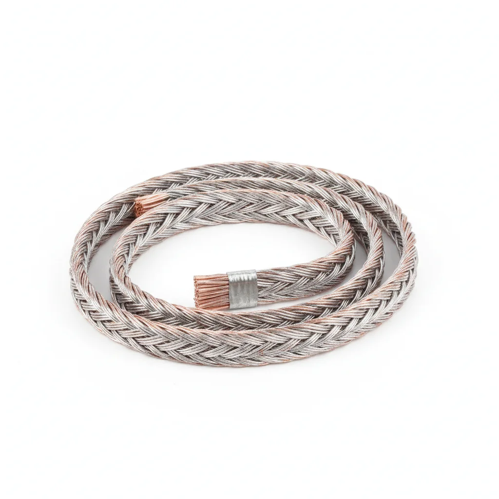
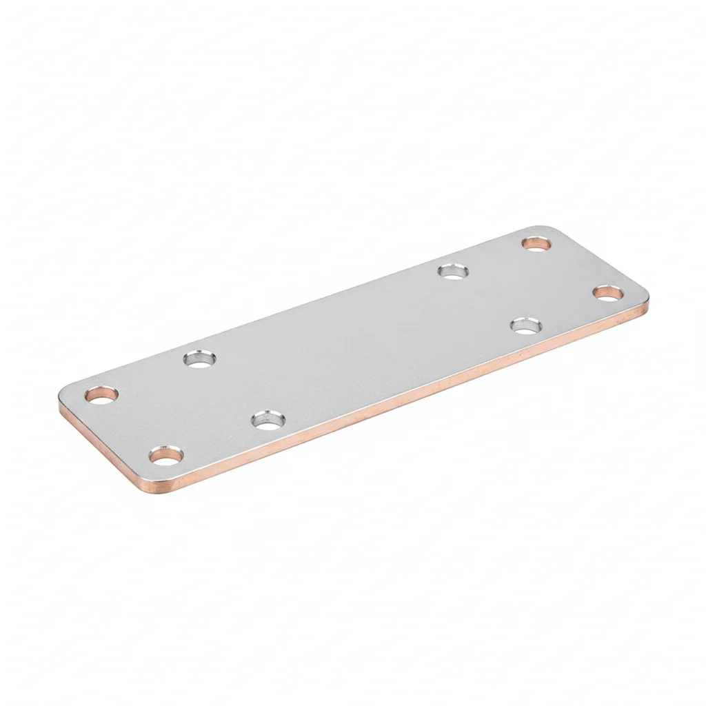
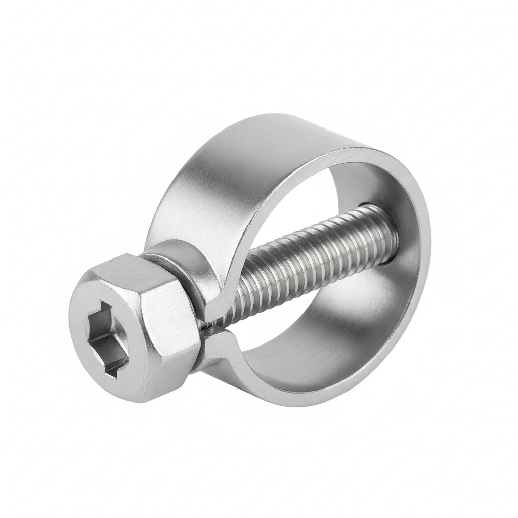
| Copper Braid Grounding Strap | Copper Braid Grounding Strap (Tower Base) | Copper Terminal | Grounding Clamp | |
|---|---|---|---|---|
| SPEC | 35mm² Tinned | 50mm² Tinned | 35/50mm² Hydraulic Crimp | Fits 10-50mm Round Steel |
| MATERIAL | T2 Tinned Copper ≥8μm | T2 Tinned Copper | T2 Tinned Copper | 304 Stainless Steel |
| GRADE | IEC 62305 Class II | IEC 62305 | / | A2-70 |
| FINISH | HDG >=55um per ISO 1461 | HDG >=55um per ISO 1461 | HDG >=55um per ISO 1461 | HDG >=55um per ISO 1461 |
| CORROSION | C3 (ISO 12944-2) | C3 (ISO 12944-2) | C3 (ISO 12944-2) | C3 (ISO 12944-2) |
| TEMP | -20°C to +80°C | -20°C to +80°C | -20°C to +80°C | -20°C to +80°C |
| WEIGHT | ~0.5 kg/piece | ~0.5 kg/piece | ~0.5 kg/piece | ~0.5 kg/piece |
| MOQ | 100 pcs | 100 pcs | 100 pcs | 100 pcs |
| PACK | VCI paper + carton | VCI paper + carton | VCI paper + carton | VCI paper + carton |
| STD | ISO 898-1, GB/T 3098.1 | ISO 898-1, GB/T 3098.1 | ISO 898-1, GB/T 3098.1 | ISO 898-1, GB/T 3098.1 |
| USE | Flange Bridging Grounding | Tower Base to Grounding Grid Main Connection | Braid Terminal | Braid to Grounding Electrode Connection |
PROCEDURE
- Clean the flange contact surfaces with a solvent to remove oil and debris, ensuring bare metal for reliable grounding contact.
- Crimp the 35mm² tinned copper braid with copper terminals using a hydraulic crimper, verifying the crimp joint meets ≥60% of the braid breaking force.
- Position the braid diagonally across the flange, using 304 stainless steel M12 bolts with A2-70 spring washers. Tighten in a star pattern to the specified torque.
- Apply copper-based conductive grease over the terminal-to-flange interface to seal against moisture and reduce galvanic corrosion.
- Measure contact resistance across each braid end with a micro-ohmmeter; confirm readings are below 1mΩ and log results for the QA record.
COMMON ERRORS
| ✕ WRONG | CONSEQUENCE | ✓ CORRECT |
|---|---|---|
| Using an undersized braid (e.g., 16mm²) for a 150kA Class II flange bridge | Under a lightning strike, the braid vaporizes instantly, disconnecting the grounding path and risking arcing damage to flange seals and bolts. | Select a 35mm² tinned copper braid per IEC 62305 Class II requirements, and verify the cross-section matches the lightning protection class. |
| Installing the braid without tinning or conductive grease at the copper-steel connection | Galvanic corrosion forms a Cu₂O oxide layer, raising contact resistance from <0.1mΩ to >10mΩ and causing grounding resistance to exceed the ≤0.2Ω limit of IEC 62305-3. | Use braids with a tin coating ≥8μm and apply copper-based conductive grease to the terminal-flange interface to prevent oxidation. |
| Crimping the terminal with a tool that does not achieve full hydraulic compression | A loose crimp increases resistance and may overheat or fail under lightning current, breaking the grounding path. | Perform a tensile test after crimping to ensure the joint holds at least 60% of the braid's breaking force. |
MAINTENANCE
During annual inspections, test the contact resistance at both ends of 30% of the flange bridging braids; replace any braid showing green copper rust (Cu₂(OH)₂CO₃) covering >10% of its surface, or if resistance exceeds 1mΩ for two consecutive checks. Re-torque flange bolts if loosening is detected, and reapply conductive grease at connections as needed.
Plan B · Coastal/High Lightning Area Enhanced Grounding
C4 Harsh per ISO 12944-2
| Copper Braid Grounding Strap (Reinforced) | Copper Braid Grounding Strap (Tower Base Reinforced) | Copper-Based Conductive Grease | Grounding Clamp | |
|---|---|---|---|---|
| SPEC | 50mm² Tinned Double | 70mm² Tinned | 100g/tube | Fits 10-50mm |
| MATERIAL | T2 Tinned Copper | T2 Tinned Copper | Copper-Based | 316 Stainless Steel |
| GRADE | IEC 62305 Class I | IEC 62305 Class I | Contact Resistance <5μΩ·cm² | A4-70 |
| FINISH | HDG >=55um per ISO 1461 | HDG >=55um per ISO 1461 | HDG >=55um per ISO 1461 | HDG >=55um per ISO 1461 |
| CORROSION | C3 (ISO 12944-2) | C3 (ISO 12944-2) | C3 (ISO 12944-2) | C3 (ISO 12944-2) |
| TEMP | -20°C to +80°C | -20°C to +80°C | -20°C to +80°C | -20°C to +80°C |
| WEIGHT | ~0.5 kg/piece | ~0.5 kg/piece | ~0.5 kg/piece | ~0.5 kg/piece |
| MOQ | 100 pcs | 100 pcs | 100 pcs | 100 pcs |
| PACK | VCI paper + carton | VCI paper + carton | VCI paper + carton | VCI paper + carton |
| STD | ISO 898-1, GB/T 3098.1 | ISO 898-1, GB/T 3098.1 | ISO 898-1, GB/T 3098.1 | ISO 898-1, GB/T 3098.1 |
| USE | Redundant Double Bridging per Flange | Tower Base to Grounding Grid Main | Apply to All Grounding Connection Surfaces | Coastal + High Lightning Area Grounding |
PROCEDURE
- Degrease flange mating surfaces with acetone and verify roughness Ra <3.2μm before installing the 50mm² tinned double braids.
- Apply copper-based conductive grease (contact resistance <5μΩ·cm²) to all contact surfaces, including terminal faces and bolt threads.
- Position two 50mm² braids diagonally at 180° across each flange, securing with 316 stainless steel A4-70 clamps.
- Tighten bolts in a cross-pattern to spec, then verify 10% with a calibrated torque wrench, logging environmental conditions.
- Perform a pull-test on a 5% sample of crimped terminals to ensure ≥60% of braid breaking force, replacing any below threshold.
- Seal connections with weatherproof coating and install corrosion monitoring coupons near critical joints.
COMMON ERRORS
| ✕ WRONG | CONSEQUENCE | ✓ CORRECT |
|---|---|---|
| Installing only one braid per flange instead of the diagonal 180° pair | If that single braid vaporizes under a 200kA strike, the flange loses continuity and arcing damages bolt surfaces. | Always mount two 50mm² tinned braids diagonally to provide redundancy and balanced current sharing. |
| Using uncoated copper braid in a salt-laden coastal environment | Copper oxidizes to Cu₂O, raising contact resistance from <0.1mΩ to >10mΩ, failing IEC 62305-3's ≤0.2Ω requirement. | Specify tinned copper with ≥8μm tin and apply copper-based conductive grease at every joint. |
MAINTENANCE
Inspect all flange bridging braids at each overhaul window, measuring contact resistance on a 30% random sample; replace any braid showing green Cu₂(OH)₂CO₃ covering >10% of surface or with resistance exceeding 1mΩ, per annual pre-lightning-season checks.
Plan C · Offshore Wind Farm / Highest Grade
C5-M Extreme per ISO 12944-2
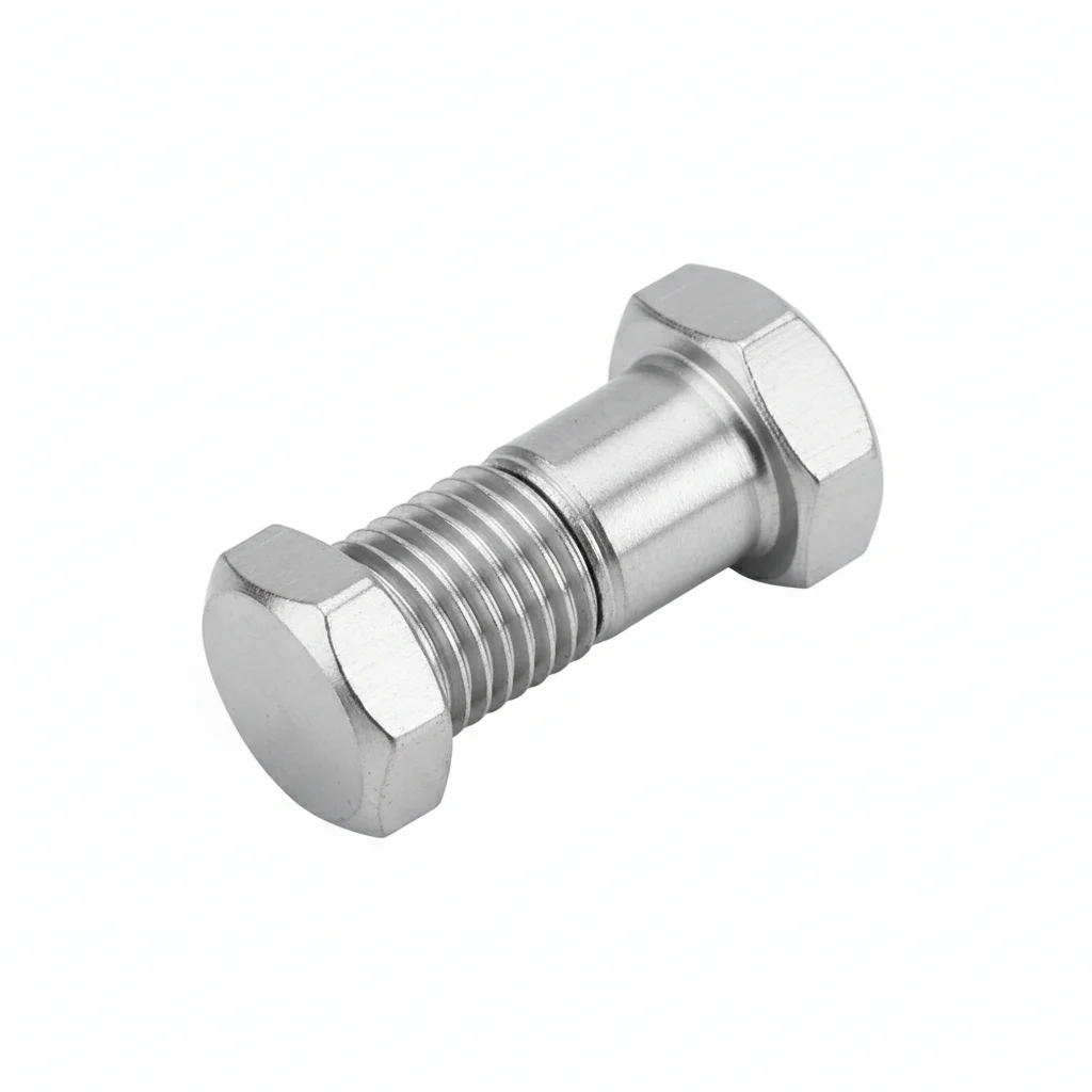
| Silver-Plated Copper Braid | Double-Bolt Grounding Terminal | Silver-Based Conductive Grease | |
|---|---|---|---|
| SPEC | 50mm² Silver-Plated | 50-70mm² | 50g/tube |
| MATERIAL | T2 Silver-Plated Copper | 316L Stainless Steel | Silver-Based |
| GRADE | IEC 62305 Class I+ | A4-80 | Contact Resistance <1μΩ·cm² |
| FINISH | HDG >=55um per ISO 1461 | HDG >=55um per ISO 1461 | HDG >=55um per ISO 1461 |
| CORROSION | C3 (ISO 12944-2) | C3 (ISO 12944-2) | C3 (ISO 12944-2) |
| TEMP | -20°C to +80°C | -20°C to +80°C | -20°C to +80°C |
| WEIGHT | ~0.5 kg/piece | ~0.5 kg/piece | ~0.5 kg/piece |
| MOQ | 100 pcs | 100 pcs | 100 pcs |
| PACK | VCI paper + carton | VCI paper + carton | VCI paper + carton |
| STD | ISO 898-1, GB/T 3098.1 | ISO 898-1, GB/T 3098.1 | ISO 898-1, GB/T 3098.1 |
| USE | Offshore Platform Full Tower Grounding | Offshore Platform Braid Termination | All Connection Points in Marine Environment |
PROCEDURE
- Degrease all connection surfaces with MEK and verify surface roughness Ra <1.6μm before mounting silver-plated braids.
- Apply silver-based conductive grease (contact resistance <1μΩ·cm²) to every terminal face and bolt thread for marine-grade protection.
- Route 50mm² silver-plated braids along the full tower grounding path, securing with 316L stainless steel A4-80 double-bolt terminals.
- Tighten terminals with a hydraulic tensioner to spec, then verify 10% via PMI to confirm material grade for compliance audit.
- Run dye-penetrant NDT on 10% of crimped terminals; replace any showing crack indications.
- Coat all exposed connections with marine sealant and install permanent condition-monitoring sensors on critical grounding paths.
COMMON ERRORS
| ✕ WRONG | CONSEQUENCE | ✓ CORRECT |
|---|---|---|
| Using tinned copper instead of silver-plated braid in an offshore salt-spray environment | Tin oxide forms over time, increasing contact resistance and risking ground path failure during a lightning event. | Choose silver-plated copper braid, which maintains <1μΩ·cm² even in C5-M marine conditions. |
| Omitting the rotating grounding device at the blade root | Lightning current from the blade (80%+ of strikes) cannot cross the non-conductive pitch bearing oil film, diverting into pitch control cables and destroying electronics. | Install a dedicated rotating grounding device rated for 200kA with redundant brush contacts, and test continuity before each lightning season. |
MAINTENANCE
Inspect all grounding connections at each overhaul window, including rotating grounding brush wear (replace when ≥5mm worn, typically after 3-5 years); verify contact resistance on 30% sample and replace any braid with cracks or discoloration at crimps.
REFERENCED STANDARDS
Referenced Standards
SUPPLIER CAPABILITY
Quality, Delivery & Customization
Quality Control
- ✓MTC material certificates with every batch
- ✓Key parts sampled for hardness/salt spray/torque coefficient
- ✓100% inspection or AQL sampling before shipment
Delivery
- ✓Standard parts made to order: 7-15 days
- ✓Custom parts: 25-45 days
- ✓FOB/CIF/DDP supported
Customization
- ✓Drawing review and material matching
- ✓Non-standard sizes/heads/threads
- ✓Small-batch prototyping supported
Certification
- ✓Material certificates (MTC)
- ✓Spectrographic analysis reports
- ✓Salt spray test reports (on request)
MOQ: No MOQ for standard parts; custom parts assessed by process complexity
FAQ
FAQ
RELATED READING
Keep Reading & Next Step
BEYOND TECHNICAL SPECS
Finding the right factory, controlling quality, delivering on time — that's the real challenge. We cover fasteners, rubber, plastics, industrial textiles. One team, end to end.
SEE CAPABILITIES →